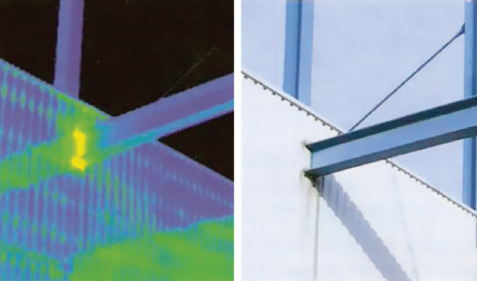
While advanced materials, triple glazing, and air-tight envelopes have improved insulation efficiency, large amounts of heat energy continue to escape the building unimpeded through thermal bridges formed wherever structural steel penetrates the envelope in the form of balconies, canopies, beams, columns, or rooftop equipment supports.
WHAT IS THERMAL BRIDGING?
A thermal bridge is simply a component that exhibits higher conductivity than the materials surrounding it. In the case of steel buildings, any structural steel element and numerous design elements penetrating the insulated building envelope constitute a thermal bridge. Even a conventional masonry support angle bolted to a steel beam or concrete slab can create a significant thermal bridge around the entire edge of a building.
Thermal bridging is categorized as either “linear,” relating to a unit of length such as a roof rafter, shelf angle, or a wall stud, or as “point,” referring to a single or repeated localized penetration of the building envelope. Point thermal bridging examples include cantilevered beams supporting balconies or façade components, and rooftop columns supporting mechanical systems.
Thermal bridging through linear heat transfer has been specifically addressed in model building codes such as ASHRAE 90.1, but less attention has been paid to point transmittance at penetrations of the building envelope.
Thermal modeling used to determine the total thermal performance of a building envelope combines the total value of heat transfer from linear, point, and clear field transmittances. The clear field transmittance is often denoted as the “U” value and is the rate of thermal energy transfer through a wall assembly without anomalies. A lower U value indicates a higher performance wall assembly. A point transmittance and a linear transmittance is the increase in thermal energy loss relative to a clear field assembly. Catalogs of thermal bridging values by assembly exist in ASHRAE and other model code developers.
The rate of heat flow through a thermal bridge depends largely on thermal conductivity of the material penetrating the envelope, with carbon steel exhibiting the greatest conductivity of the most common structural building materials. In the comparison below, k equals conductivity, or the ability of a material to transmit heat, in terms of energy that passes in unit time through unit area of a material per unit thickness per degree of temperature difference.
- Structural steel (k = 47 W/mK)
- Stainless steel (k = 16 W/mK)
- Concrete (k = 1.9 W/mK)
- Plywood (k = 0.14 W/mK)
CONSEQUENCES OF THERMAL BRIDGING
Steel elements that form a thermal bridge between heated building interiors and cold exterior environments rapidly conduct heat energy through the insulated building envelope, with several outcomes:
Thermal energy (heat) loss. Thermal bridging interrupts the otherwise continuous insulation of the building envelope, wasting heat energy as shown in thermal images.
The most recent releases of model building codes by ANSI, ASHRAE, IECC, and other bodies reflect an increased concern for energy efficiency, offering an array of pathways to energy-standards compliance. Mitigating heat loss from thermal bridges is an important component of achieving compliance in jurisdictions where these codes have been enacted.
Most codes suggest at least three approaches demonstrating continuous insulation compliance: the prescriptive path, the building envelope trade-off method, and the whole building energy modeling method. The latter two methods can achieve compliance without addressing the problem of thermal bridging at all. However, the 2016 ASHRAE 90.1 codes do require all uninsulated assemblies to be separately modeled. These assemblies would include balconies, canopies, sunshades, screen walls, and other building envelope penetrations. For builders pursuing LEED, Net Zero, Passive House, and other green building certifications, prevention of thermal bridging is essential to meeting these higher standards.
Chilled interior floors. In the case of balconies, cantilevered “eyebrows,” canopies, and other extensions of interior floors, heat lost through thermal bridges chills adjacent interior surfaces.
Increased energy costs and carbon emissions. To compensate for chilled interior surfaces, building occupants often raise thermostat settings or use portable heaters, further increasing energy costs and carbon emissions.
Interior condensation, mold, and rust. New buildings face condensation, mold, and rust problems that older buildings do not, due to airtight vapor barriers. Whereas air leakage causes older buildings to equalize with low exterior humidity levels in the range of 25 percent during winter, newer air-tight vapor barriers mean that HVAC systems run less frequently, causing interior humidity levels to reach up to 50 percent during winter. Higher humidity lowers temperatures and energy required to maintain comfortable interiors, but it also lowers the dew point near cold interior penetrations, causing condensation to form on the steel structures and adjacent surfaces. Rust formation on the structure itself can compromise its integrity and require maintenance, while mold formation on adjacent studs, insulation and sheetrock can expose occupants to airborne mold years before it spreads to visible wall and ceiling surfaces, exposing developers and building owners to liability costs.
Exterior ice formation. The exterior portion of the beam can warm sufficiently to melt snow and ice, which then refreezes as water flows away from the thermal bridge, causing ice dams, pooling water, structural loading, corrosion, and/or falling ice.
CLOSING THOUGHT
Addressing thermal bridges will improve insulation efficiency so large amounts of heat energy will not continue to escape the building. Look for part two of this article in the next issue of MCS as options to thermal bridging are presented.
For More Information
For more about Schöck North America and thermal bridging, visit www.schock-na.com.
Modern Contractor Solutions, March 2020
Did you enjoy this article?
Subscribe to the FREE Digital Edition of Modern Contractor Solutions magazine.


