If the saying goes, “The whole is more than the sum of its parts,” then all those parts must absolutely be important in creating a dynamic final product. This adage is especially true at Chicago’s O’Hare International Airport, one of the world’s busiest, which is in the midst of one of the country’s largest construction projects.
The O’Hare Modernization Program (OMP) is transforming O’Hare International Airport’s airfield from an outdated system of intersecting runways into a modern parallel runway configuration to reduce flight delays and increase capacity well into the future. Managed by the Chicago Department of Aviation (CDA), when the OMP is complete, O’Hare will have eight runways: six east-west parallel runways and two crosswind runways.
Three major OMP projects have already been completed, including two runway projects. A third runway project, Runway 10C/28C, is under construction and nearing completion. It will be an Airplane Design Group VI capable runway, built to accommodate new aircraft, such as the Boeing 747-8 and Airbus A-380.
But, of course there are many important “parts” that make up the completion of the Runway 10C/28C project, including the demolition and relocation of outdated buildings that would otherwise simply be in the way when the new runways are put in. But even before that, new underground utilities must be installed such as gas, electric, potable water, and sewer.
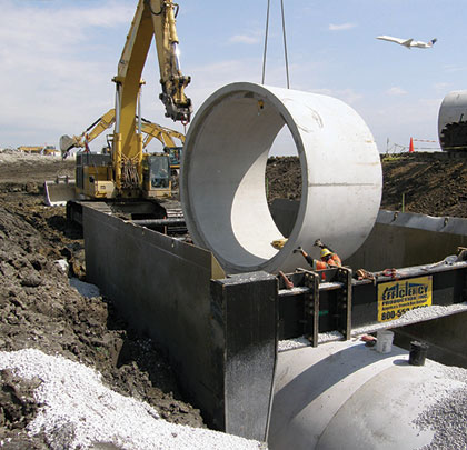
Chicago-based Walsh Construction Company recently completed installing a new storm sewer that is 15,000 linear feet of 144-inch concrete pipe. A total of 188 individual pipe sections were installed in the ground 25 feet below the future runway.
BIG PIPE, DEEP DEPTH
Whenever working underground, personnel safety because a primary factor. With such extreme parameters on this project, it was even more so. Simply selecting the right shoring system becomes critically important. Should the contractor use trench shields? Sheeting? Slide Rail?
Walsh’s first step in determining the best trench protection system was to call Efficiency Production—a leading manufacturer of trench shoring and shielding equipment—to discuss the feasibility of designing trench shields that might work for the big-pipe, deep-trench dilemma.
“Walsh really wanted to use trench boxes if possible, so it was really a matter of coming up with the engineering and design that might work for this project and fit Walsh’s needs,” says Mike West, Efficiency’s vice president of engineering. “We’ve come up with some very unconventional designs for trench shields in the past that have been very successful, so we really relished the challenge of this project.”
“Overall I’d say Efficiency gets an A+ for their work, both building the (trench) boxes and the help they provided on-site,” says Mark Fournier, Walsh’s project manager. “There was a lot of synergy on the project,” he adds.
THREE SOLUTIONS
Essentially, there were three key factors to the project that needed to be addressed in the design of a trench shield or combination of trench shields: the depth of the pipe (more than 25 feet deep); the size of the pipe (12 feet in diameter); and the connection of two junction boxes (20-foot square, 18-foot tall).
One limitation to trench shields is simply how deep it can safely go in any particular soil condition. Efficiency manufactures trench shields engineered to safely reach depths of 25 feet, but with a standard shield sidewall height of 8 or 10 feet. In order to get the shield to the proper grade for Walsh’s project, Efficiency designed a set of 10-foot-tall, 30-foot-long trench shields to stack on each other. The remaining depth was achieved by precutting, or benching, the trench 10 feet.
Another limitation of any trench shield is pipe clearance. Trench boxes require spreaders or other cross-members that connect the two sidewalls. Steel pipe is the most common spreader device, but spreader pipe takes up a lot of space. So Efficiency proposed the use of a spreader arch on one end of the box, which allows extra clearance on the trailing end. In this instance, the wide-flange arch connects to the sidewalls of both the top and bottom stacked shields.
With the use of a Komatsu PC-800 excavator and a Link Belt 248 crane, Walsh was able to install the 8-foot-long pipe sections two at a time in the 30-foot-long, 20-foot-wide box before digging forward the box about 20 feet while the arch straddled the pipe on the back end. Laying the pipeline actually became a fairly conventional procedure for a very unconventional situation.
STRUCTURE INSTALLATION
With the big-pipe problem solved, Walsh then turned to another difficult challenge; safely installing two large precast junction boxes in two spots along the pipeline. Extra pipe clearance was needed coming into and out of the structures. So Walsh asked Efficiency to design, deliver, and help assemble on-site a second set of stacked trench shields with spreader arches on both ends.
In addition to the crane and PC-800, Walsh had a complete arsenal of heavy equipment on the job including a CAT 345 excavator, a Volvo L120 front-loader, a John Deere 850 bulldozer, and three CAT 740 trucks to haul dirt, stone, and backfill.
Walsh completed the pipeline project in May 2012. Runway 10C/28C is scheduled to be commissioned in the fourth quarter of 2013. ■
About The Author:
James McRay is the director of marketing and media for Efficiency Production, Inc. He can be reached at 800.552.8800; jmcray@efficiencyproduction.com. For more information, visit www.efficiencyproduction.com.
_________________________________________________________________________
Modern Contractor Solutions, May 2013
Did you enjoy this article?
Subscribe to the FREE Digital Edition of Modern Contractor Solutions magazine.

25 Feet in the Deep


